GEOTECHNICAL ENGINEERING
GARLAND
HomeGeophysicsSeismic tomography (refraction/reflection)

Seismic Tomography for Subsurface Imaging in Garland, TX

Evidence-based design. Reliable delivery.

LEARN MORE

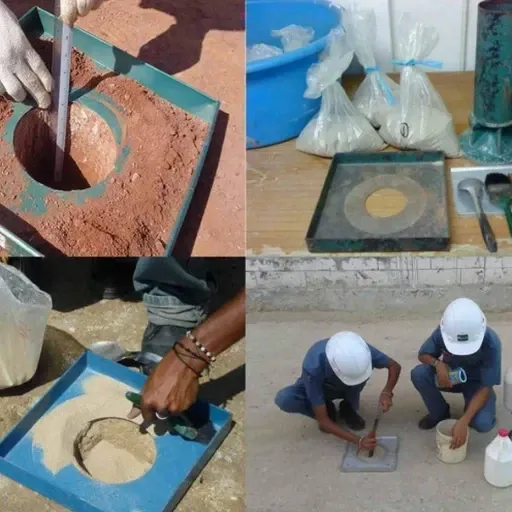
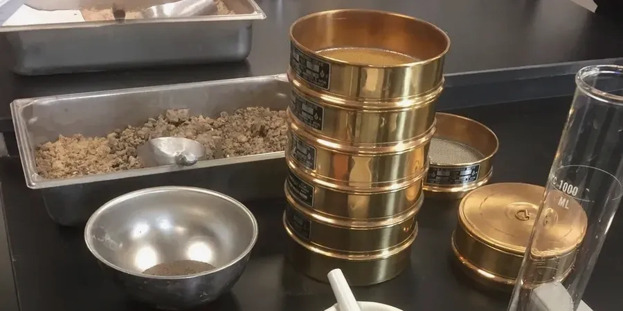
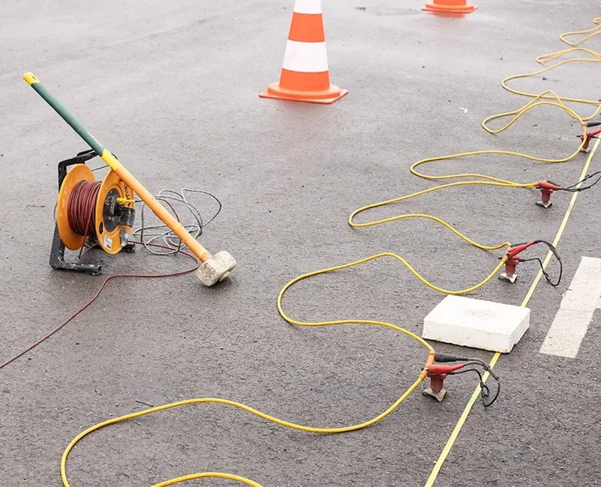
Garland’s expansion across the Blackland Prairie, with its deep clay soils and scattered limestone shelves, means every construction project here sits on a layered geological puzzle. We have seen too many projects stall because the borehole spacing missed a five-foot drop in bedrock or a soft channel fill that only continuous profiling could catch. Seismic tomography fills that gap. The method sends shear and compression waves through the subsurface, and our processing turns travel-time data into a velocity cross-section that reveals stratigraphy in detail. For projects near Lake Ray Hubbard or along the Rowlett Creek floodplain, where alluvial deposits shift over short distances, this geophysical approach becomes a cost-saver. We often pair it with SPT drilling to calibrate velocities against actual blow counts at key locations, giving you both coverage and verification in one campaign.

Seismic velocity sections let you see between the boreholes—where the real geotechnical risk usually hides.

Our service areas

Methodology and scope

Garland sits at roughly 550 feet above sea level, but the real story is underground—the Eagle Ford Shale and Austin Chalk formations dip and pinch out across the metro area, creating sharp lateral contrasts that standard borings sometimes misread. A seismic tomography survey uses geophone arrays spaced from 5 to 20 feet, and we switch between P-wave refraction and S-wave reflection depending on whether the target is rippability, water table mapping, or bedrock topography. On a recent warehouse site near I-30, the velocity gradient mapped a buried paleo-channel at 28 feet that four evenly spaced borings had completely missed. Instead of over-excavating the entire pad, the owner limited removal to the channel zone. The data integrates directly into BIM and civil grading models. When karst features or dissolution cavities are suspected in the limestone, we combine tomography with resistivity profiling to cross-validate anomalies before recommending mitigation.
Seismic Tomography for Subsurface Imaging in Garland, TX
Technical reference — Garland

Local considerations

We reviewed a site off Broadway Boulevard where the developer had already poured grade beams before discovering a 15-foot drop in bedrock under one corner of the slab. The original geotech report relied on four borings that showed consistent refusal at 22 feet. Seismic tomography ran in two perpendicular lines revealed a steeply dipping limestone ledge that the borings had straddled without intersecting. The differential settlement potential was severe. The fix required underpinning two column lines and injecting low-mobility grout into the transition zone. That single survey cost less than one percent of the total structural retrofit. On any site within the Austin Chalk outcrop belt, ignoring lateral velocity contrasts is a gamble with expensive consequences. We recommend at least one tomography profile across the long axis of the building footprint whenever bedrock is shallower than 40 feet.

Need a geotechnical assessment?

Reply within 24h.

Email: [email protected]

Reference standards

ASTM D5777 – Standard Guide for Seismic Refraction, ASTM D7128 – Standard Guide for Seismic Reflection, ASCE 7 – Minimum Design Loads (Site Classification via Vs), IBC 2021 – Chapter 16 Structural Design

Technical data

ParameterTypical value
Geophone array24-48 channels, single or multi-line spread
Source typeAccelerated weight drop or sledgehammer on steel plate
Depth of investigationTypically 30 to 100 ft below grade
P-wave resolutionLayer thickness down to 3-5 ft detectable
S-wave applicationMapping low-velocity zones, water table, soft clay
Output deliverables2D velocity cross-sections, depth-to-bedrock maps, DXF/PDF
ASTM referenceASTM D5777 (seismic refraction) and D7128 (reflection)

Frequently asked questions

How much does a seismic tomography survey cost for a typical Garland commercial lot?

For a standard commercial parcel (1 to 3 acres), budgets typically range from US$2,350 to US$4,570 depending on the number of geophone lines, shot points, and whether both refraction and reflection processing are required. We provide a firm quote after reviewing your site plan and target depth.

How does seismic tomography improve on standard SPT borings?

SPT borings give you excellent point data on soil strength and sample recovery. Seismic tomography fills the space between borings with a continuous velocity cross-section, revealing lateral changes in stiffness or bedrock elevation that discrete sampling can miss entirely. The two methods complement each other—we calibrate velocity models with boring data for maximum reliability.

Can you run the survey without damaging the existing pavement or landscaping?

Yes. We use surface geophones coupled to the ground with small spikes or weighted bases, and the seismic source is a non-invasive impact plate. No drilling or heavy equipment. The setup leaves no lasting marks and works on asphalt, compacted gravel, or grass.

How deep can seismic tomography see in Garland soils?

Depth depends on the geophone spread length and the source energy. With a 230-foot spread and an accelerated weight drop, we routinely image 50 to 100 feet below grade in the clays and shale of the Blackland Prairie. For deeper targets, we extend the line or use a larger energy source.

What deliverables do we receive after the fieldwork?

You get 2D velocity cross-sections with interpreted layer boundaries, a depth-to-bedrock contour map, and a technical report summarizing the velocity model and its geotechnical implications. Raw SEG-2 field files are included on request for independent review.

Location and service area

We serve projects in Garland and surrounding areas.

View larger map